CoBo-CPU : Introduction
Question: What do you do when you have started too many projects and have yet another idea?
Answer: You tell yourself this is too great of an idea to not add it to the pile of unfinished things.
Why? Because I can!The Idea
What if a Turing Machine would actually be a (somewhat) useful CPU?
When Alan Turing layed out his idea of a universal computing machine he designed it as simple as possible. He, being a mathematician made his life "easy" by defining some of the parts of that machine as infinite: The memory for example. He also decided to separate the "Data Storage" from the "Program Storage" which is not ideal for a simple implementation of a CPU.
So, unlike the classic definition of a Turing Machine my implementation does not use infinite amount of memory and does not separate data from machine code. In fact, my design uses just 16 bits of address space which is quite far away from infinity.
The CoBo Design
CoBo stands for "Cobbled & Bodged". Which describes the hardware implementation perfectly.
One of the reasons I started this project was that I have tons of LS74HC*** logic chips laying around which I wanted to use for – something.
One of the goals – a challenge, rather – was to only use my existing stock and not buying any more logic chips for that project. Because of this situation, some of the solutions seem quite strange and cumbersome. For example, the implementation of the ALU, which could be done using actual full adders but is instead implemented with "discrete" AND and XOR logic chips.
The Architecture
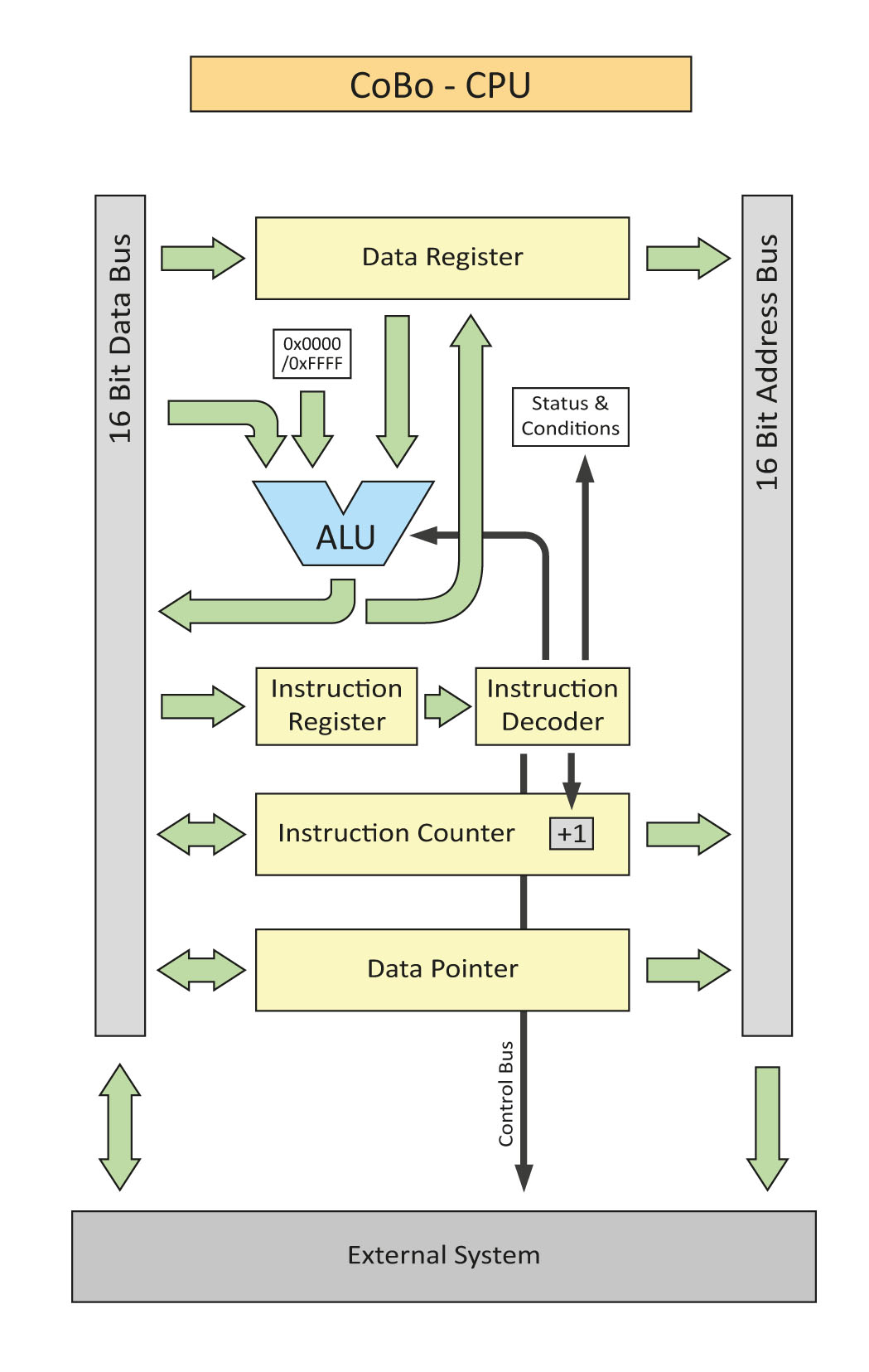
As you can see, it’s not much of an architecture compared to other simple CPU designs. But the goal was to only add the things that turn the impractical design of the turing machine into a (somewhat) practical CPU.
That includes more than 1 bit of number range and an ALU that can do some level of actual computation. The things that are similar to the turing machine are the instruction counter which represents the "state" of the machine, the data pointer which represents the position of the "read head" and the data register which represents the contents read by the "read head". Things like the instruction register and the instruction decoder are more or less necessary "infrastructural" elements of the system.
Some details about the architecture:- All registers are 16bit wide
- The instruction counter is an actual counter that can be parallel loaded like a register
- The ALU is only capable of the following operations: +1, -1, AND, OR, XOR, Shift left/right
- There’s a carry and a zero flag
- Every instruction can be conditional
- Separate memory and IO address space
- Every instruction is executed in one cycle
- Interrupt input (must be queried in software)
So Far So Good
Before I started to design the actual hardware I designed the entire thing in LogiSim to see if it would even work. It does. It also gave me the opportunity to iron out some kinks in the system that aren't immediatly obvious. Like, where do I get the second operand from when doing a two-operand computation while writing the result into memory. Hence the [0x0000 / 0xFFFF] block in the diagram above. One of the two values can be chosen as the second operand. The first operand is always the data register.Comments
- dude
wrote:hello world01. February, 2023
